Setting Up
This section briefly describes how to set up and start using
an oscilloscope - specifically, how to ground the oscilloscope, set the controls
in standard positions, and compensate the probe.
Grounding
Proper grounding is an important step when setting up to take
measurements or work on a circuit. Properly grounding the oscilloscope protects
you from a hazardous shock and grounding yourself protects your circuits from
damage.
Ground the Oscilloscope
Grounding the oscilloscope is necessary
for safety. If a high voltage contacts the case of an ungrounded oscilloscope,
any part of the case, including knobs that appear insulated, it can give you a
shock. However, with a properly grounded oscilloscope, the current travels
through the grounding path to earth ground rather than through you to
earth ground.
To ground the oscilloscope means to
connect it to an electrically neutral reference point (such as earth ground).
Ground your oscilloscope by plugging its three-pronged power cord into an outlet
grounded to earth ground.
Grounding is also necessary for taking accurate measurements with your
oscilloscope. The oscilloscope needs to share the same ground as any circuits
you are testing.
Some oscilloscopes do not require the separate connection to earth ground.
These oscilloscopes have insulated cases and controls, which keeps any possible
shock hazard away from the user.
If you are working with integrated
circuits (ICs), you also need to ground yourself. Integrated circuits have tiny
conduction paths that can be damaged by static electricity that builds up on
your body. You can ruin an expensive IC simply by walking across a carpet or
taking off a sweater and then touching the leads of the IC. To solve this
problem, wear a grounding strap (see Figure 1). This strap safely sends static
charges on your body to earth ground.
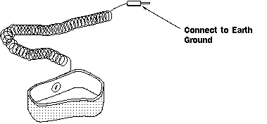
Figure 1: Typical Wrist Type Grounding Strap
After plugging in the oscilloscope, take a
look at the front panel. It is divided into three main sections labeled
Vertical, Horizontal, and Trigger. Your oscilloscope may
have other sections, depending on the model and type (analog or digital).
Notice the input connectors on your
oscilloscope. This is where you attach probes. Most oscilloscopes have at least
two input channels and each channel can display a waveform on the screen.
Multiple channels are handy for comparing waveforms.
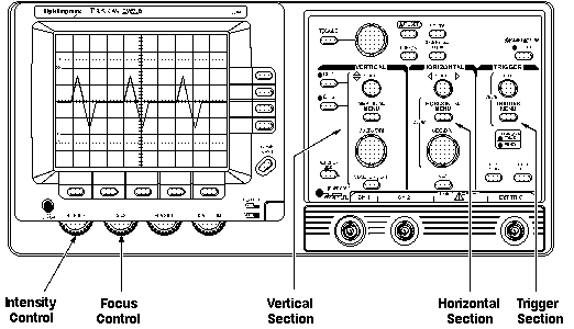
Figure 2: Front Panel
Control Sections of an Oscilloscope
Some oscilloscopes have an AUTOSET
or PRESET button that sets up the controls in one step to accommodate a signal.
If your oscilloscope does not have this feature, it is helpful to set the controls to standard positions before
taking measurements.
Standard positions include the following:
- Set the oscilloscope to display channel 1
- Set the volts/division scale to a mid-range position
- Turn off the variable volts/division
- Turn off all magnification settings
- Set the channel 1 input coupling to DC
- Set the trigger mode to auto
- Set the trigger source to channel 1
- Turn trigger holdoff to minimum or off
- Set the intensity control to a nominal viewing level
- Adjust the focus control for a sharp display
These are general
instructions for setting up your oscilloscope. If you are not sure how to do any
of these steps, refer to the manual that came with your oscilloscope. The
Controls section describes the controls in more detail.
Now you are ready to
connect a probe to your oscilloscope. It is important to use a probe designed to
work with your oscilloscope. A probe is more than a cable with a clip-on tip. It
is a high-quality connector, carefully designed not to pick up stray radio and
power line noise.
Probes are designed not to influence
the behavior of the circuit you are testing. However, no measurement device can
act as a perfectly invisible observer. The unintentional interaction of the
probe and oscilloscope with the circuit being tested is called circuit
loading. To minimize circuit loading, you will probably use a 10X attenuator
(passive) probe.
Your oscilloscope probably arrived with a passive probe as a standard
accessory. Passive probes provide you with an excellent tool for general-purpose
testing and troubleshooting. For more specific measurements or tests, many other
types of probes exist. Two examples are active and current probes.
Descriptions of these probes follow, with more emphasis given to the passive
probe since this is the probe type that allows you the most flexibility of use.
Using Passive Probes
Most
passive probes have some degree of attenuation factor, such as 10X, 100X, and so
on. By convention, attenuation factors, such as for the 10X attenuator probe,
have the X after the factor. In contrast, magnification factors like X10 have
the X first.
The 10X (read as "ten times") attenuator probe minimizes circuit loading and
is an excellent general-purpose passive probe. Circuit loading becomes more
pronounced at higher frequencies, so be sure to use this type of probe when
measuring signals above 5 kHz. The 10X attenuator probe improves the accuracy of
your measurements, but it also reduces the amplitude of the signal seen on the
screen by a factor of 10.
Because it attenuates the signal, the 10X attenuator probe makes it difficult
to look at signals less than 10 millivolts. The 1X probe is similar to the 10X
attenuator probe but lacks the attenuation circuitry. Without this circuitry,
more interference is introduced to the circuit being tested. Use the 10X
attenuator probe as your standard probe, but keep the 1X probe handy for
measuring weak signals. Some probes have a convenient feature for switching
between 1X and 10X attenuation at the probe tip. If your probe has this feature,
make sure you are using the correct setting before taking measurements.
Many oscilloscopes can detect whether you are using a 1X or 10X probe and
adjust their screen readouts accordingly. However with some oscilloscopes, you
must set the type of probe you are using or read from the proper 1X or 10X
marking on the volts/div control.
The 10X attenuator probe works by balancing the probe's electrical properties
against the oscilloscope's electrical properties. Before using a 10X attenuator
probe you need to adjust this balance for your particular oscilloscope. This
adjustment is called compensating the probe and is further described in the next section. Figure 3 shows a simple
diagram of the internal workings of a probe, its adjustment, and the input of an
oscilloscope.
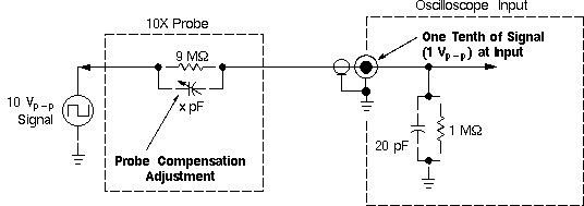
Figure 3: Typical Probe/Oscilloscope 10-to-1 Divider Network
Figure 4 shows a typical passive probe and some accessories to use with the
probe.
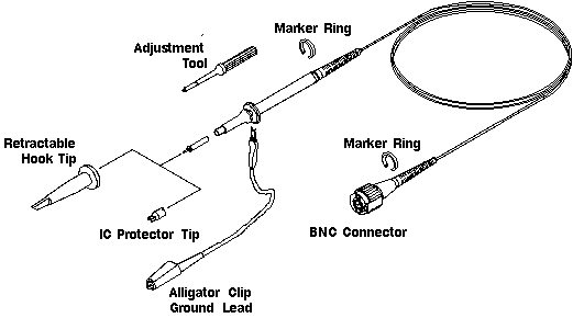
Figure 4: A Typical
Passive Probe with Accessories
Using Active Probes
Active probes provide their own
amplification or perform some other type of operation to process the signal
before applying it to the oscilloscope. These types of probes can solve problems
such as circuit loading or perform tests on signals, sending the results to the
oscilloscope. Active probes require a power source for their operation.
Using Current Probes
Current
probes enable you to directly observe and measure current waveforms. They are
available for measuring both AC and DC current. Current probes use jaws that
clip around the wire carrying the current. This makes them unique since they are
not connected in series with the circuit; they, therefore, cause little or no
interference in the circuit.
Where to Clip the Ground
Clip
Measuring a signal requires two connections: the probe tip connection
and a ground connection. Probes come with an alligator-clip attachment for
grounding the probe to the circuit under test. In practice, you clip the
grounding clip to a known ground in the circuit, such as the metal chassis of a
stereo you are repairing, and touch the probe tip to a test point in the
circuit.
Before using a passive probe, you need to
compensate it - to balance its electrical properties to a particular
oscilloscope. You should get into the habit of compensating the probe every time
you set up your oscilloscope. A poorly adjusted probe can make your measurements
less accurate. Figure 5 shows what happens to measured waveforms when using a
probe not properly compensated.
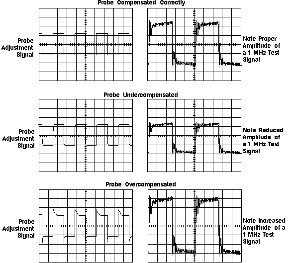
Figure 5: The Effects of Improper Probe Compensation
Most oscilloscopes have a square wave reference signal available at a
terminal on the front panel used to compensate the probe. You compensate a probe
by:
- Attaching the probe to an input connector
- Connecting the probe tip to the probe compensation signal
- Attaching the ground clip of the probe to ground
- Viewing the square wave reference signal
- Making the proper adjustments on the probe so that the corners of the
square wave are square
When you compensate the probe, always attach
any accessory tips you will use and connect the probe to the vertical channel
you plan to use. This way the oscilloscope has the same electrical properties as
it does when you take measurements.
Next Chapter: The Controls
Previous Chapter: Oscilloscope Terminology


