The Controls
This section briefly describes the basic controls found on
analog and digital oscilloscopes. Remember that some controls differ between
analog and digital oscilloscopes; your oscilloscope probably has controls not
discussed here.
Display
systems vary between analog and digital oscilloscopes. Common controls include:
- An intensity control to adjust
the brightness of the waveform. As you increase the sweep speed of an analog
oscilloscope, you need to increase the intensity level.
- A focus control to adjust the
sharpness of the waveform. Digital oscilloscopes may not have a focus control.
- A trace rotation control to align
the waveform trace with the screen's horizontal axis. The position of your
oscilloscope in the earth's magnetic field affects waveform alignment. Digital
oscilloscopes may not have a trace rotation control.
- Other display controls may let you adjust the intensity of the graticule
lights and turn on or off any on-screen information (such as menus).
Use the
vertical controls to position and scale the waveform vertically. Your
oscilloscope also has controls for setting the input coupling and other signal
conditioning, described in this section. Figure 1 shows a typical front panel
and on-screen menus for the vertical controls.
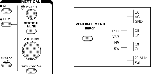
Figure 1: Vertical Controls
The vertical position control lets you
move the waveform up or down to exactly where you want it on the screen.
The volts per division (usually written volts/div) setting varies the size of
the waveform on the screen. A good general purpose oscilloscope can
accurately display signal levels from about 4 millivolts to 40 volts.
The volts/div setting is a scale
factor. For example, if the volts/div setting is 5 volts, then each of the eight
vertical divisions represents 5 volts and the entire screen can show 40 volts
from bottom to top (assuming a graticule with eight major divisions). If the
setting is 0.5 volts/div, the screen can display 4 volts from bottom to top, and
so on. The maximum voltage you can display on the screen is the volts/div
setting times the number of vertical divisions. (Recall that the probe you use,
1X or 10X, also influences the scale factor. You must divide the volts/div scale
by the attenuation factor of the probe if the oscilloscope does not do it for
you.)
Often the volts/div scale has either
a variable gain or a fine gain control for scaling a displayed signal to a
certain number of divisions. Use this control to take rise time measurements.
Coupling means the method used to connect
an electrical signal from one circuit to another. In this case, the input
coupling is the connection from your test circuit to the oscilloscope. The
coupling can be set to DC, AC, or ground. DC coupling shows all of an input
signal. AC coupling blocks the DC component of a signal so that you see the
waveform centered at zero volts. Figure 2 illustrates this difference.
The AC coupling setting is handy when the entire signal (alternating plus
constant components) is too large for the volts/div setting.
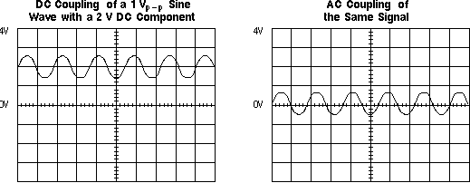
Figure 2: AC and DC Input Coupling
The ground setting disconnects the
input signal from the vertical system, which lets you see where zero volts is on
the screen. With grounded input coupling and auto trigger mode, you see a
horizontal line on the screen that represents zero volts. Switching from DC to
ground and back again is a handy way of measuring signal voltage levels with
respect to ground.
Most
oscilloscopes have a circuit that limits the bandwidth of the oscilloscope. By
limiting the bandwidth, you reduce the noise that sometimes appears on the
displayed waveform, providing you with a more defined signal display.
Most
oscilloscopes have an invert function that allows you to display a signal
"upside-down." That is, with low voltage at the top of the screen and high
voltage at the bottom.
On
analog scopes, multiple channels are displayed using either an alternate or chop
mode. (Digital oscilloscopes do not normally use chop or alternate mode.)
Alternate mode draws each channel alternately - the oscilloscope completes
one sweep on channel 1, then one sweep on channel 2, a second sweep on channel
1, and so on. Use this mode with medium- to high-speed signals, when the sec/div
scale is set to 0.5 ms or faster.
Chop mode causes the oscilloscope to draw small parts of each signal by
switching back and forth between them. The switching rate is too fast for you to
notice, so the waveform looks whole. You typically use this mode with slow
signals requiring sweep speeds of 1 ms per division or less. Figure 3 shows the
difference between the two modes. It is often useful to view the signal both
ways, to make sure you have the best view.
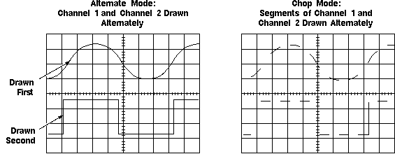
Figure 3: Multi-Channel Display Modes
Math Operations
Your
oscilloscope may also have operations to allow you to add waveforms together,
creating a new waveform display. Analog oscilloscopes combine the signals while
digital oscilloscopes mathematically create new waveforms. Subtracting waveforms
is another math operation. Subtraction with analog oscilloscopes is possible by
using the channel invert function on one signal and then use the add operation.
Digital oscilloscopes typically have a subtraction operation available. Figure 4
illustrates a third waveform created by adding two different signals together.
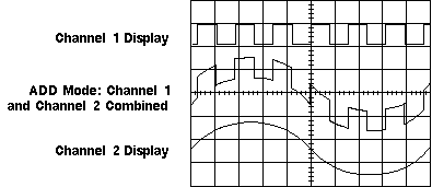
Figure 4: Adding Channels
Use the horizontal controls to position
and scale the waveform horizontally. Figure 5 shows a typical front panel and
on-screen menus for the horizontal controls.
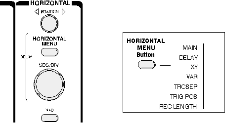
Figure 5: Horizontal Controls
Position and Seconds per Division
The horizontal position control moves the
waveform from left and right to exactly where you want it on the screen.
The seconds per division (usually
written as sec/div) setting lets you select the rate at which the waveform is
drawn across the screen (also known as the time base setting or sweep speed).
This setting is a scale factor. For example, if the setting is 1 ms, each
horizontal division represents 1 ms and the total screen width represents 10 ms
(ten divisions). Changing the sec/div setting lets you look at longer or shorter
time intervals of the input signal.
As with the vertical volts/div scale, the horizontal sec/div scale may have
variable timing, allowing you to set the horizontal time scale in between the
discrete settings.
Time Base Selections
Your
oscilloscope has a time base usually referred to as the main time base and it is
probably the most useful. Many oscilloscopes have what is called a delayed time
base - a time base sweep that starts after a pre-determined time from the start
of the main time base sweep. Using a delayed time base sweep allows you to see
events more clearly or even see events not visible with just the main time base
sweep.
The delayed time base requires the
setting of a delay time and possibly the use of delayed trigger modes and other
settings not described in this book. Refer to the manual supplied with your
oscilloscope for information on how to use these features.
Trigger Position
The trigger
position control may be located in the horizontal control section of your
oscilloscope. It actually represents "the horizontal position of the
trigger in the waveform record." Horizontal trigger position control is only
available on digital oscilloscopes.
Varying the horizontal trigger position allows you to capture what a signal
did before a trigger event (called pretrigger viewing).
Digital oscilloscopes can provide pretrigger viewing because they constantly
process the input signal whether a trigger has been received or not. A steady
stream of data flows through the oscilloscope; the trigger merely tells the
oscilloscope to save the present data in memory. In contrast, analog
oscilloscopes only display the signal after receiving the trigger.
Pretrigger viewing is a valuable troubleshooting aid. For example, if a
problem occurs intermittently, you can trigger on the problem, record the events
that led up to it and, possibly, find the cause.
Your oscilloscope may have special
horizontal magnification settings that let you display a magnified section of
the waveform on-screen.
XY Mode
Most oscilloscopes have
the capability of displaying a second channel signal along the X-axis (instead
of time). This is called XY mode; you will find a longer discussion later in this book.
The trigger
controls let you stabilize repeating waveforms and capture single-shot
waveforms. Figure 6 shows a typical front panel and on-screen menus for the
trigger controls.
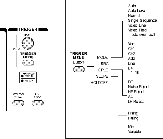
Figure 6: Trigger Controls
The trigger makes repeating waveforms appear static on the oscilloscope
display. Imagine the jumble on the screen that would result if each sweep
started at a different place on the signal (see Figure 7).
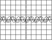
Figure 7: Untriggered Display
Trigger Level and Slope
Your oscilloscope may have several
different types of triggers, such as edge, video, pulse, or logic. Edge
triggering is the basic and most common type and is the only type discussed in
this book. Consult your oscilloscope instruction manual for details on other
trigger types.
For edge triggering, the trigger level and slope controls provide the basic
trigger point definition.
The trigger circuit acts as a comparator. You select the slope and voltage
level of one side of the comparator. When the trigger signal matches your
settings, the oscilloscope generates a trigger.
- The slope control determines whether the trigger point is on the rising or
the falling edge of a signal. A rising edge is a positive slope and a falling
edge is a negative slope.
- The level control determines where on the edge the trigger point occurs.
Figure 8 shows you how the trigger slope and level settings determine
how a waveform is displayed.
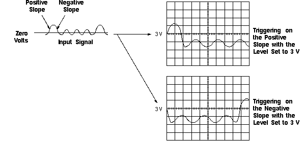
Figure 8: Positive and Negative Slope Triggering
The
oscilloscope does not necessarily have to trigger on the signal being measured.
Several sources can trigger the sweep:
- Any input channel
- An external source, other than the signal applied to an input channel
- The power source signal
- A signal internally generated by the oscilloscope
Most of the time
you can leave the oscilloscope set to trigger on the channel displayed.
Note that the oscilloscope can use an alternate trigger source whether
displayed or not. So you have to be careful not to unwittingly trigger on, for
example, channel 1 while displaying channel 2.
The trigger mode determines whether or not
the oscilloscope draws a waveform if it does not detect a trigger. Common
trigger modes include normal and auto.
In normal mode the oscilloscope only
sweeps if the input signal reaches the set trigger point; otherwise (on an
analog oscilloscope) the screen is blank or (on a digital oscilloscope) frozen
on the last acquired waveform. Normal mode can be disorienting since you may not
see the signal at first if the level control is not adjusted correctly.
Auto mode causes the oscilloscope to sweep, even without a trigger. If no
signal is present, a timer in the oscilloscope triggers the sweep. This ensures
that the display will not disappear if the signal drops to small voltages. It is
also the best mode to use if you are looking at many signals and do not want to
bother setting the trigger each time.
In practice, you will probably use both modes: normal mode because it is more
versatile and auto mode because it requires less adjustment.
Some oscilloscopes also include special modes for single sweeps, triggering
on video signals, or automatically setting the trigger level.
Trigger Coupling
Just as you
can select either AC or DC coupling for the vertical system, you can choose the
kind of coupling for the trigger signal.
Besides AC and DC coupling, your
oscilloscope may also have high frequency rejection, low frequency rejection,
and noise rejection trigger coupling. These special settings are useful for
eliminating noise from the trigger signal to prevent false triggering.
Sometimes
getting an oscilloscope to trigger on the correct part of a signal requires
great skill. Many oscilloscopes have special features to make this task easier.
Trigger holdoff is an adjustable period of time during which the
oscilloscope cannot trigger. This feature is useful when you are triggering on
complex waveform shapes, so that the oscilloscope only triggers on the first
eligible trigger point. Figure 9 shows how using trigger holdoff helps create a
usable display.
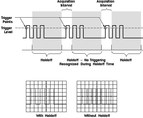
Figure 9: Trigger Holdoff
Acquisition Controls for Digital
Oscilloscopes
Digital oscilloscopes have settings that let you control how
the acquisition system processes a signal. Look over the acquisition options on
your digital oscilloscope while you read this description. Figure 10 shows you
an example of an acquisition menu.
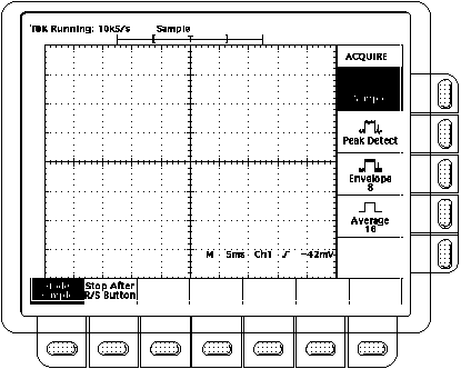
Figure 10: Example of an Acquisition Menu
Acquisition modes control how waveform
points are produced from sample points. Recall from the first section that
sample points are the digital values that come directly out of the
Analog-to-Digital-Converter (ADC). The time between sample points is called the
sample interval. Waveform points are the digital values that are stored in
memory and displayed to form the waveform. The time value difference between
waveform points is called the waveform interval. The sample interval and the
waveform interval may be but need not be the same. This fact leads to the
existence of several different acquisition modes in which one waveform point is
made up from several sequentially acquired sample points. Additionally, waveform
points can be created from a composite of sample points taken from multiple
acquisitions, which leads to another set of acquisition modes. A description of
the most commonly used acquisition modes follows.
- Sample Mode: This is the
simplest acquisition mode. The oscilloscope creates a waveform point by saving
one sample point during each waveform interval.
- Peak Detect Mode: The
oscilloscope saves the minimum and maximum value sample points taken during
two waveform intervals and uses these samples as the two corresponding
waveform points. Digital oscilloscopes with peak detect mode run the ADC at a
fast sample rate, even at very slow time base settings (long waveform
interval), and are able to capture fast signal changes that would occur
between the waveform points if in sample mode. Peak detect mode is
particularly useful for seeing narrow pulses spaced far apart in time.
- Hi Res Mode: Like peak
detect, hi res mode is a way of getting more information in cases when the ADC
can sample faster than the time base setting requires. In this case, multiple
samples taken within one waveform interval are averaged together to produce
one waveform point. The result is a decrease in noise and an improvement in
resolution for low speed signals.
- Envelope Mode: Envelope
mode is similar to peak detect mode. However, in envelope mode, the minimum
and maximum waveform points from multiple acquisitions are combined to form a
waveform that shows min/max changes over time. Peak detect mode is usually
used to acquire the records that are combined to form the envelope waveform.
- Average Mode: In average
mode, the oscilloscope saves one sample point during each waveform interval as
in sample mode. However, waveform points from consecutive acquisitions are
then averaged together to produce the final displayed waveform. Average mode
reduces noise without loss of bandwidth but requires a repeating signal.
Stopping and Starting the Acquisition System
One of the greatest
advantages of digital oscilloscopes is their ability to store waveforms for
later viewing. To this end, there are usually one or more buttons on the front
panel that allow you to stop and start the acquisition system so you can analyze
waveforms at your leisure. Additionally, you may want the oscilloscope to
automatically stop acquiring after one acquisition is complete or after one set
of records has been turned into an envelope or average waveform. This feature is
commonly called single sweep or single sequence and its controls are usually
found either with the other acquisition controls or with the trigger controls.
In digital
oscilloscopes that can use either real-time sampling or equivalent-time sampling
as described earlier, the acquisition controls will
allow you to choose which one to use for acquiring signals. Note that this
choice makes no difference for slow time base settings and only has an effect
when the ADC cannot sample fast enough to fill the record with waveform points
in one pass.
Other Controls
So far we have described the basic controls that a
beginner needs to know about. Your oscilloscope may have other controls for
various functions. Some of these may include:
- Measurement cursors
- Keypads for mathematical operations or data entry
- Print capabilities
- Interfaces for connecting your oscilloscope to a computer
Look
over the other options available to you and read your oscilloscope's manual to
find out more about these other controls.
Next Chapter: Measurement Techniques
Previous Chapter: Setting Up


