Home Page
The Method And Circuit For Testing Integrated Circuits Using Terminal Characteristics
Adrian Virgil CRACIUN
Selections
Abstract: This paper presents an original method and a practical system implementation for testing virtually any kind of integrated circuit (IC). The testing method is based on the plotting of IC terminal characteristics, by measuring few voltage-current pairs for all the IC terminal pairs. The testing block diagram of the testing system, the schematics of some of the circuits and some of theirs design formulae are presented.
Key words: Integrated circuits testing, Logical level shift circuits,
Testing method fundamentals
The integrated circuits (IC-s) testing is a time consuming task. In order to get shorter test time, structural testing methods were developed. These testing methods were initially applied for digital IC-s, based on modeling faults and simulation the fault effect on the IC behavior in test conditions. The digital tested IC is powered, the gates works normally and the internal IC structure is verified.
The method presented in this paper, tests the behavior of the IC at its terminals and the tested IC is not powered normally. A current source is applied between two IC pins at a time, the current injected is modified, the voltages are measured and the terminal characteristic is plotted for the two pins. When all the pin combinations (for a good IC) were tested, a structural model can be developed for this IC, specifying the accepted limits for the terminal characteristics. Using this model, a different IC (same type) can be tested in the previously presented manner. This testing method is a structural one because it tests the IC structure (from the terminal point of view) and is a static testing method because the dc signals were used.
The proposed method can test numerous different kind of IC: digital, analog or mixed signal IC, made with different technologies: bipolar, CMOS or BiCMOS. It is obvious that testing IC-s with this method only is not enough because an IC declared error free (with this testing method) is not necessarily good, it can have functional or parametrical errors. This testing method can be used for the IC suspected to be damaged because of an electrical shock (that generally produce a different behavior of the IC at the terminals where the shock appeared).
Comparing this method with the classical ones, one can see that the main advantage is the simplicity and coming with this: the reduced cost, high testing speed and the testing system portability. The second advantage is that most IC-s can be tested using this method. The main disadvantage, specific of most structural testing methods, is the uncertain positive answer. Some supplementary test method (functional tests for example) can be used.
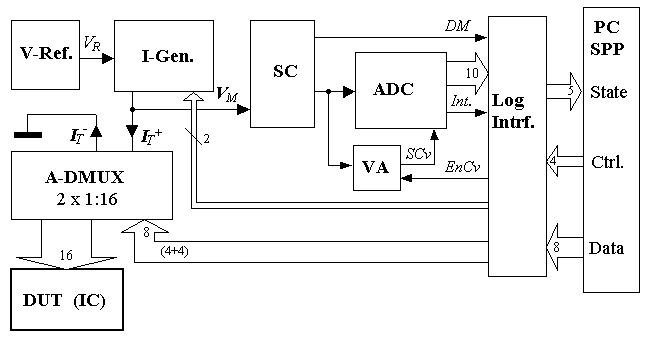
A testing system, utilizing the principles presented above, was realized based on a personal computer (PC) used for test control, test sequences generation, data analyze and storage.
The component blocks and their role are:
- I-Gen.
– Current Generator, can generate 4 precise currents, the chosen of one of these can be made using 2 control lines;
- DUT (IC) – Device Under Test, the Integrated Circuit that is tested can have up to 128 pins;
- ADC – Analog to Digital (A/D) Converter is a fast 10 bit converter, started by SCv and generating the Int. signal at the end of A/D conversion;
- V-Ref. – Voltage Reference, (5.00V) used by I-Gen. and ADC;
- A-DMUX –Analog Demultiplexer (2 x 1:16), defines the way the current flows from I-Gen. to DUT, settles the input and the output pin. The chosen of these pins is made by the selection lines (4 selection bits were used for every pin, the 16 pin IC-s was considered);
- SC – Signal Conditioner circuit, modifies the voltage value (between the IC pins) to be in the ADC accepted domain. The SC allows two input domains: 0…2V and 0…16V The output digital signal DM (Domain of Measurement) indicates which domain was automatically selected by the SC;
- VA – Validation of Analog signal, a circuit that automatically detects the end of the transitory period and starts the A/D conversion;
- PC SPP – PC Standard Parallel Port with data, control and state buses.
- Log. Intrf. – Logical Interface, controls the data flow between the interface and SPP;
The analogue signals used are:
- VR – Reference voltage;
- IT+, IT- – Current for test, input and output (equal), currents respectively;
- VM –Measured voltage (positive, with respect to the ground GND).

Fig. 1. Block diagram of the data acquisition system for IC structural testing.
Some blocks of the system, which use original sub-circuits, will be presented.
The current generator ... Signal conditioning circuit ... The control circuit ...
Conclusions
A fully functional model, for DIL (dual-in-line) 8, 14 or 16 pins IC testing system (using terminal characteristics) was practically implemented. More than 300 IC-s (more than 30 different types, digital and analog), were tested using the testing method presented in the paper and the practical problems with the testing system were solved. The next research step is to develop "structural terminal models" for different IC's type.
Metoda si circuit de testare a circuitelor integrate
prin analiza caracteristicilor de terminal
Rezumat: Lucrarea prezinta o metoda originala si un sistem realizat experimental, care permit testarea circuitelor integrate de orice tip. Metoda de testare se bazeaza pe trasarea caracteristicilor de terminal, realizata prin masurarea unor perechi tensiune-curent pentru toate perechile de terminale ale circuitului integrat. In lucrare se prezinta schema bloc a sistemului, schemele de principiu si formulele de dimensionare ale unora dintre circuitele componente.
Cuvinte cheie: Testare circuitelor integrate, circuit de deplasare de nivel.
Home Page

