Home Page
Settling Time Instant Detector
for Steady-State Transient Signals
Adrian Virgil CRACIUN, George NICOLAE
Transilvania University of Brasov, Electronics and Computer Department
Selections
Abstract: This paper describes an original circuit that accomplishes detection of transient response end during the steady-state signal acquisition. The presented circuit can therefore be used in triggering a data acquisition system, for example when steady-state characteristics such as current-to-voltage terminal characteristics, have to be plotted. Operating principle, schematic diagram and major characteristics of the proposed detection circuit are analyzed on the basis of an experimental hardware implementation.
Index Terms : Steady-state signals, data acquisition systems.
Introduction
One of the most important parameters of a data acquisition system is its overall speed. In this paper, the case of static signals measurement is considered. To be more specific, the example of "The structural testing of integrated circuits using terminal characteristics" [1] is considered. This test method verifies the behavior of the tested integrated circuit (IC) at its terminals. A dc current is applied between two IC pins and the voltage (between the tested pins) is measured; the two pin I-V terminal characteristic is drawn and compared with a standard one. This testing method is a steady-state testing method because the dc parameters of the electrical signals were used.
In such cases, the acquisition speed depends not only on the speed of the analog to digital converter (ADC) but also on the transient response of the measured circuit. To ensure maximum accuracy of steady-state measurements, the signal should be allowed to settle, i.e. the acquisition process is to be started only after the transient period of the signal. …
An efficient strategy, presented in this paper, consist in utilizing an additional circuit that triggers the acquisition when the transient response of the acquired signal ends. The advantages of this strategy are: a small overall acquisition time, a low data traffic at the computer interface and a lower quantity of information that must be processed by the computer of the data acquisition system. The additional delay due to the detection method, can be optimized to become negligible compared with the overall acquisition time.
The detector operating principle
The transient period ends when the analyzed signal becomes constant. The circuit presented in this paper detects the equality between the input signal and the signal that results when the input signal is fed through a lag network (that delays and integrates it). When the two signals are equal, the output digital signal (that triggers the ADC), is generated. For a constant input signal (the ideal case), the output signal is generated after a time that depends on the time constant of the lag network and on the accepted difference between the two signals that are compared. The block diagram of the detector is presented in Fig.1.
 Fig. 1. The block diagram of the detection circuit.
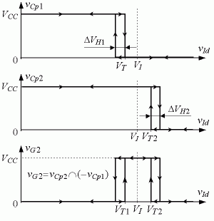
Considering the signal slope polarity, during the transient regime, the delayed signal (at the lag circuit output) can be smaller (a) or greater (b) than the input signal (for a positive slope or for a negative slope of vI, respectively). Two hysteresis comparators are used to compare the input signal and the delayed signal, Cp1 for case (a) and Cp2 for case (b). Hysteresis is necessary in order to avoid oscillations at the comparator outputs [2]. Gate G2 combines the outputs of the comparators as can be seen in Fig.2. The comparators are designed with threshold and hysteresis voltages as shown in Fig.2. The threshold voltages VT2 and VT1 are close to the input voltage value VI.
The delay circuit Dly2 rejects the unwanted state which occur when the comparator outputs signals are equals.
 Fig. 2. Comparators Cp1, Cp2 and gate G1 output signals
as function of the delayed input signal.
G1 restores the logic levels and allows the control of the output state from the digital part of the system. The output digital signal is SCv (start of conversion, whose active state is "0"). The input digital signal EnCv (enable conversion) should be "1" to enable the conversion and can be used also to start a new conversion with a "0"–"1" sequence; which is possible only after the comparators indicates the end of the transient mode (the other input of G1 should be "1").
The Implementation ... Experimental Results ...
Conclusions
This paper presents an original circuit that detects the end of the transient mode of analogic signals. The presented detection circuit proves itself useful in data acquisition system during steady-state signal measurement such as plotting the terminal characteristics of a device. The main advantage of this circuit is a reduced overall acquisition time, while keeping a low data flow between the acquisition circuit and the computer that controls the acquisition. Circuit design can be customized by choosing the appropriate time constants, in order to meet the user's specific requirements. For a very precise acquisition, with an error of one or two low significant bits, a good strategy is to use an additional acquisition step which verifies that the results difference is within the accepted error range.
In order to verify the method error of the actual implementation, few recurrent acquisition were performed after the basic acquisition (that is triggered by the VA circuit). The error of the initially acquired voltage is less than 10mV (2 low significant bits, for the 5V, 10 bit ADC) in more than 90% of the cases (more than 100,000 different acquisitions were performed).
Home Page


